System overview
The Uni-Fy system implements a wireless open access network gateway.
Its main features are:
- support for multiple external authentication providers
- extensible support for several authentication techniques
- firewalling
- accounting
Its modular design is intended for easy implementation of novel features such
as QoS control, context-dependent services and traffic shaping and modeling.
The system is fully implemented in C++ as a collection of user-space applications.
Linux was chosen as operating system, but portability to other operating systems,
in particular Windows, is one of the main criteria in development; however,
linux-specific optimizations, such as the implementation as kernel-space modules,
are being considered.
Basic network configuration
Figure 1.1:
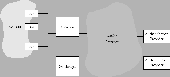
An overall view of the Uni-Fy system.
|
|
Figure 1.1 shows an overall view of the proposed network
components.
- The blocks ``AP'' denote wireless access points.
- The Gateway component is basically a layer-3 switch with some
additional ad-hoc functionalities (however, a configurable router
or a firewall with enough flexibility should be applicable):
it checks packets that are directed from and to authorized clients and
puts them into the right interface.
- The Gatekeeper component receives unauthorized packets from the Gateway:
packets are subjected to processingan and are used to trigger
events such as an authentication procedure. The authentication procedure will
involve the client, the Gateway (for packet forwarding),
the Gatekeeper and an authentication provider, possibly chosen among many. The
role of every component and the type of interaction
depend on the authentication mechanism, and shall be discussed later.
For sake of clarity, connections among components are shown as separate
wires in Figure 1.1. However, many logical connections can
be shared by separate virtual LANs on the same
wire; the Gateway and Gatekeeper components can even reside in the same machine.
If the AP supports an evoluted operating system, the
whole solution could be collapsed into a single piece of hardware:
however, high performance requirements may force
physical separation of the components.
The Gateway component bridges the wireless LAN and the other side, which may
be a corporate LAN, a WAN, a point-to-point
line with several network components in it. Non-interference with other
network components is an important requirement.
The source code is available from Twelve website http://twelve.dit.unitn.it/tools.html.
After performing the source checkout, all necessary code is contained in the wilmaproject/gateway
subfolder, which shall be referred to as the ``root'' directory of the program. The root directory
contains the following items:
Common/ contains source code which is used both by the Gateway and by the Gatekeeper programs.
Gateway/ contains the Gatewayspecific source code.
GateKeeper/ contains the Gatekeeperspecific source code.
parameters/ contains the runtime configuration files for the two programs.
web.TEMPLATE/ contains web page templates and code for provider choice, for authentication and for system interrogation.
specs/ contains system documentation and specifications (and this document itself).
Makefile is the overall makefile for the whole project.
Doxyfile is the Doxygen configuration file for automatic API documentation.
- Some
restart scripts to automate the execution of the programs.
The system has been tested on Linux (Redhat 9 and Debian distributions) and Cygwin machines.
The following packages must be installed:
- GNU C++ compiler (others have not been tested);
- Standard libraries.
On Linux systems:
- glibc (no particular requirements about version, probably also libc5 is good, please send us feedback);
- libpthread (for POSIX threads, it should be present by default);
- libpcap version 0.7 or greater (for layer 2 packet capture, also present by default on many systems).
Note that versions 0.6 and below miss some key functionalities.
On Cygwin systems:
- the cygwin DDLs
- libpcap for Windows, retrievable from
http://winpcap.polito.it/
The system has been tested with version 3.1beta3.
Please be sure to download both the installer and the developer's pack. After installing it, please edit
Gateway/Makefile and set the correct path in WPCAP_PATH for winpcap includes and
libraries.
If all requirements are satisfied, compilation is simply achieved by tiping make at the root directory.
No errors or warnings should appear: please notify us of any compiler warning at the contact address provided above.
Compilation of the full documentation (this manual and API description) requires LaTeX and the Doxygen documentation system.
The latter can be found at
http://www.stack.nl/~dimitri/doxygen/
RPMs and other distributions are probably included in OS installation CDs. The Cygwin version can be selected
in the standard Setup program. To generate documentation, type
make doc
from the home directory. The doc directory shall be generated with both HTML and LaTeX contents, while the present
document will be created in the specs directory.
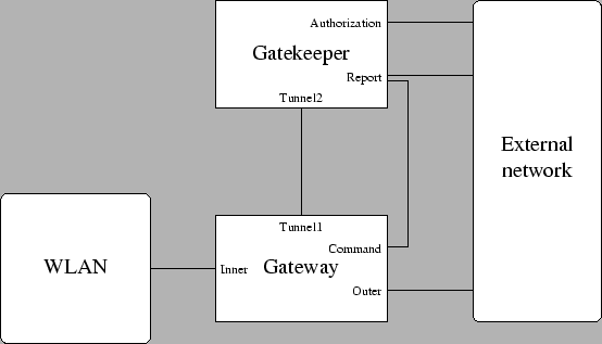
Figure 4.1:
Reference for configuration
|
|
Next, the system must be configured. Please refer to Figure 4.1 for interface names:
- The ``inner'' interface, i.e. the Gateway interface to the wireless LAN.
- The Gateway's tunnel endpoint interface to the Gatekeeper.
- The ``outer'' interface, i.e. the Gateway interface to the external network.
- The Gateway ``Command'' interface, contacted by the Gatekeeper in order to change a client's status.
- The Gatekeeper's tunnel endpoint interface to the Gateway.
- The Gatekeeper report interface.
- The Gatekeeper authorization interface.
In most systems, some of these interface correspond to the same physical device. Usually, interfaces ``Tunnel1'', ``Outer''
and ``Command'' are the same (the Gatekeeper resides on the outer network segment of the Gateway), while the Gatekeeper has only one interface,
so that ``Tunnel2'', ``Report'' and ``Authorization'' are equal.
If the Gateway and the Gatekeeper reside on the same machine, then interfaces ``Tunnel1'', ``Tunnel2'' and ``Command'' are local
(their IP is 127.0.0.1), while interfaces ``Outer'', ``Report'' and ``Authorization'' coincide.
After identifying each physical interface and associating it to the ones reported in Figure 4.1,
the IP address of each interface must be found.
Only for interfaces ``Inner'' and ``Outer'', also the system name is needed. On UNIX systems,
the name is eth , where is a small index;
all required information can be borrowed from the output of , where is a small index;
all required information can be borrowed from the output of ifconfig.
On Cygwin, two names are required for each interface: the first is recognized by the Cygwin networking primitives, and
is similar to the UNIX name; the second is the Windows resource name, beginning by ``\Device...''
used by Winpcap, and can be obtained from the capture menu of Ethereal (www.ethereal.com).
Next, a pool of IP addresses must be allocated for the DHCP server. The usual way to do this is ask to the network administrator
of your structure. Currently, the system works for a subset of a class C network (255 addresses), some more work is required to
extend it to a larger IP address pool.
Interface constraints
Some conditions must be met by the network interfaces of the system.
- The IP of the ``Inner'' interface of the Gateway must lie in the same class C network as the DHCP pool.
- The ``External Network'' must contain a web proxy server, a web server and a DNS server, if necessary in the Gatekeeper machine.
- Two more addresses in the DHCP subnet must be reserved:
- the gateway that shall be declared by the DHCP server,
- the DHCP server itself.
Both IPs shall be managed (actually, faked) by the Gateway program through the ``Inner'' interface,
and must not be assigned to any network card.
- The Gatekeeper's ``Tunnel2'' and ``Report'' IPs must be accessible from the Gateway.
- The Gatekeeper's ``Report'' IP must be accessible from the loca webserver.
- The Gatekeeper's ``Authorization'' interface must be accessible from the Authentication providers, i.e. from the outside (unless authentication is managed internally).
- The Gateway's ``Tunnel1'' interface must be reachable from the Gatekeeper.
- The Gateway's ``Command'' interface must be reachable from the Gatekeeper.
Edit a file in the parameters directory having a .gw extension (use one of the enclosed templates).
The file format is free, only ``equal'' (``='') signs are important and introduce the values of the configuration
parameters, that must be reported in the given sequence. Ports should remain as they are. Parameters have the following meaning:
- Inner interface network --
The class C network containing the DHCP pool.
- Inner interface netmask --
The corresponding netmask.
- Inner interface ARP domain --
The inner interface must respond to ARP queries for the class C network gateway,
i.e. the first of the two reserved and unassigned addresses in 4.3.1.
- Inner interface ARP mask --
Usually, the above address is the only one that must respond to ARP queries, so a full mask is adequate.
- Inner interface properties name --
The inner device name.
- Inner interface capture name --
The inner device name for pcap (same as above in UNIX systems, different for winpcap).
- Outer interface network --
The network accessible via the outer interface is the whole world (in principle), so a null address is usually good.
- Outer interface netmask --
For the same reason, a null mask is adequate.
- Outer interface ARP domain --
The ``outer'' interface must respond to ARP queries on behalf of wireless clients in order
to work as gateway, so the class C subnet containing the DHCP pool should usually be written.
- Outer interface ARP mask --
The corresponding class C netmask.
- Outer interface properties name --
The outer device name.
- Outer interface capture name --
The outer device name for pcap (same as above in UNIX systems, different for winpcap).
- Outer interface gateway --
The IP address of the external network gateway.
- Tunnel IP --
The IP address of the ``Tunnel1'' interface.
- Tunnel listening UDP port --
The corresponding UDP port number.
- Command interface listening IP --
The IP address of the ``Command'' interface.
- Command interface listening TCP port --
The corresponding TCP port number.
- Gatekeeper's tunnel IP --
The IP address of the ``Tunnel2'' interface, as reported in the Gatekeeper configuration (see below).
- Gatekeeper tunnel listening port --
The corresponding TCP port number.
- Gatekeeper's reporter IP --
The IP address of the ``Report'' interface, as reported in the Gatekeeper configuration (see below).
- Gatekeeper reporter listening port --
The corresponding TCP port number.
- Dropped packet sink IP --
The router can optionally send all dropped ethernet frames
to an external application listening to a specified IP address and UDP port.
- Dropped packet sink UDP port --
UDP port of the sink application.
If no sink is required, then the firso parameter must be set to 0.0.0.0,
the second to 0.
- DNS servers --
A semicolon-separated list of IP addresses of authorized DNS servers.
- Initial HTTP server --
IP address of the initial web server for authentication purposes.
- Proxy servers --
A semicolon-separated list of IP addresses of the authorized Proxy servers. The only supported port at this moment is
port 3128.
- Run mode --
Determination of the runtime mode (1 to detach from console and run as daemon, 0 otherwise)
- Log file --
Output destination for daemon mode.
- Transparent mode --
Should be kept to zero. A nonzero value lets all packets flow through the gateway without authentication
(only DHCP requests are treated), and can be used for debugging and testing.
- PID file --
File where the process ID must be written to (may be left blank).
Edit a file in the parameters directory having a .gk extension (use one of the enclosed templates).
The file format is free, only ``equal'' (``='') signs are important and introduce the values of the configuration
parameters, that must be reported in the given sequence. Ports should remain as they are. Parameters have the following meaning:
- Authorization IP --
The IP address of the ``Authorization'' interface. Note that the authorization IP address must be reachable from the
authentication providers, so in most cases it should be exposed to the Internet on a public IP address (this is not the case
of a self-contained system).
- Authorization port --
The TCP port.
- Report IP --
The IP address of the ``Report'' interface. The interface is also used by the choose.php web page to obtain
the list of available authentication providers. Therefore, the IP address should be reachable from the local web server.
- Report port --
The TCP port.
- Dispatcher IP --
The IP address of the ``Tunnel2'' interface.
- Dispatcher listening port --
The UDP port.
- Gateway tunnel IP --
The IP address of the ``Tunnel1'' interface of the Gateway.
- Gateway tunnel port --
The UDP port.
- Gateway command IP --
The IP address of the ``Command'' interface of the Gateway.
- Gateway command port --
The TCP port.
- DHCP class C network IP --
The base network address of the DHCP pool.
- DHCP first assignable IP --
The smallest IP address that can be assigned by the DHCP plugin; remember that some
addresses are reserved.
- DHCP last assignable IP --
The largest IP address in the DHCP pool.
- IP of DNS server --
The IP address of the DNS server.
- IP of wireless gateway --
The reserved IP used as wireless gateway.
- IP network mask --
The class C network mask 255.255.255.0.
- IP network domain --
Domain name of the network.
- Fake address of the DHCP server --
The reserved IP used as DHCP server.
- Short lease time --
The lease time (in seconds) for unauthorized clients. Usually in the tens.
- Long lease time --
The lease time (in seconds) for authorized clients. Usually in the thousands.
The following info applies to the captive portal method, currently the only available in the system.
- redirection URL --
URL towards which an unauthorized client must be directed. See 4.3.4 for details.
- redirection URL when no proxy is set --
If the client's proxy is not set, then a warning webpage should be displayed. Its URL must be reported here.
- Proxy configuration file URL --
If the (Microsoft proprietary?) proxy configuration feature of the proxy server is used,
this field must contain the URL of the WPAD.DAT configuration file,
if possible in the gateway's local HTTP server (usually in the local branch,
where a sample file can be found).
- Authorization renewal time --
Expiration time (in seconds) of an authorization. A client must renew his authorization before it expires, otherwise
the whole authentication process will begin.
- Run mode --
Type 1 to detach the process from the console (run in daemon mode), 0 otherwise.
- Status table dump file --
File containing an up-to-date version of the status table, used to recover the relevant system status information
after a crash or an interruption.
- Program log file --
File containing the log of the system.
- PID file --
File where the process ID must be written to (may be left blank).
- RelayActivated --
Type 1 to use DHCP Realay agent to interact with external DHCP server.
Type 0 if Uni-Fy built-in DHCP server is used (if 0, following
parameters are not required).
- DHCPServerIP --
IP address of DHCP server in external LAN.
- OuterInterfaceIP --
IP address of interface that interacts with DHCP server (Authorization
or Report IP address).
- NatPublicIP --
IP address of interface that interacts with DHCP server. It must be
equal to OuterInterfaceIP when DHCP does not pass through NAT.
- InnerInterfaceIP --
IP address of interface that interacts with internal LAN. The gateway
for internal network.
- DHCPServerListenerPort --
Port number of the listener. Default is 67 (defined by standard)
- DHCPClientThinkServerPort --
Port number for infromation that must be sent to client. Default is 67 (defined by standard)
- InnerInterfaceName --
The inner device name.
This section of the file contains one quadruple for each authentication provider.
- Name --
Name of the provider, to be displayed in the choice page.
- URL --
URL of the provider's authentication page.
- Prefix --
Prefix of all URLs of that provider that must be accessed by unauthorized clients.
- Domain --
The canonical domain name of the host, usually the domain part of the above URL.
- IP --
IP of the provider's web server.
A provider record with an empty URL field has a special meaning:
it is the description of the access provider choice page.
After the last provider, an empty ``Name'' field ends the list.
Following, a section with perpetually authorized, therefore this section
must be handled with much care.
Note: from Version UniFy-20060412 there is a separation between
authorization and IP assignment. A user that must insert user-id and
password to provide his own credentials, receives always a dynamic IP
address (both built-in DHCP server and DHCP Relay is used) and it is not
in the following list. A
perpetually authorized user can receive a dynamic IP address or can have
a static IP address on his own machine.
- Name --
Name of the client.
- Email --
Email address of the person responsible for the client.
- MAC --
Ethernet MAC address of the client.
- IP --
built-in DHCP server
- IP address that must be attributed to the client, if the
client require static configuration or reserved IP.
- 0.0.0.0 if the IP address is requested trhough DHCP
transaction.
DHCP Relay server
- IP address that must be attributed to the client, if the
client has manual configuration of IP in the machine.
- 0.0.0.0 if the IP address is requested through DHCP
transaction. Realted to configurationin DHCP server, the
provided IP address can be always the same or can change.
After the last static IP, an empty ``Name'' field ends the list.
Web server configuration
The ``captive portal'' authentication method requires the presence of one or more web servers,
that must be accessible via the proxy server.
The web server must be configured so that an alias is hooked to the web subdirectory
of the system. Three directories are contained in web:
local contains all pages related to the first access of an unauthorized user:
instructions about setting the proxy, choice of the authentication provider.
auth contains all pages related to authentication and authorization renewal.
status contains all pages that can be used to show the system status.
The access server can be located in the Gateway or in the Gatekeeper machine. It must expose the local directory.
The only configuration needed is in file choose.php, where the correct port number must be set
in variable gk_reporter_port.
If the automatic proxy configuration feature is activated, it is important to expose the local
directory via tha wireless interface of the gateway. In this case, the wpad.dat file must be
configured with the correct proxy parameters.
Optionally, the status directory can be exposed. In this case, files index.php and client.php
must connect to the ``Report'' interface of the Gatekeeper.
The authentication provider must expose the subdirectory web/auth via a secure connection (https).
An authentication provider must contain some user authentication data. These can be provided by a
RADIUS or LDAP service, by a MySQL database or in an internal table, or by any combination of such services.
For instance, a centralized LDAP service can provide authentication for all regular users, while
some temporary users can be managed by a MySQL table in a local machine.
Description of available services is provided in the config/config.inc.php, that must be configured according
to the chosen authentication system.
Two more pages are provided in config to add people to a MySQL database and to change password.
If communication ports are changed with respect to their default values (ranging from 54270 to 54273),
then all PHP pages must be modified accordingly.
From the base directory, the programs can be launched with the following commands:
GateKeeper/gatekeeper parameters/[gatekeeper config].gk
Gateway/gateway parameters/[gateway config].gw
It is important to start the Gatekeeper program before the Gateway. Both programs output a log, either to the standard output
or to the specified log file, according to the specified run mode. Events such as DHCP offers and acknowledgments, authorizations
and revocations are recorded in the log by the Gatekeeper. When authorization to a client is revoked, the Gatekeeper logs
the traffic generated by that client during that session.
To ease program restart, the bash shell script ``restart.sh'' is provided in the main directory to
be configured (CONFIGBASENAME variable). When launched, it will stop any gateway or gatekeeper program instance
and launch the programs in the correct order. If the previous program termination left any dangling TCP socket,
the script will repeatedly attempt to restart the program until socket timeouts free the required resources.
In order to ensure higher availability, the shell script ``check_if_running'' is provided;
modify its parameters according to the installation and make cron invoke it
periodically by adding a line to the root's crontab (command ``crontab -e'')
such as
0,5,10,15,20,25,30,35,40,45,50,55 * * * * /root/bin/check_if_running
The Uni-Fy system can be configured in different topologies:
with the Gatekeeper and Gateway programs installed on a single machine or
on two machines.
In this section, public IP address means an IP address that
can be managed by the external LAN; in particular, if the external
network is the Internet, the term has its common meaning, and the
public IP address must be a real public IP address.
On the other hand, if the external LAN is a private LAN with
a border gateway and a proxy server, the public IP address
can be any IP address that can be routed in the LAN.
In this section we focus on
four configurations:
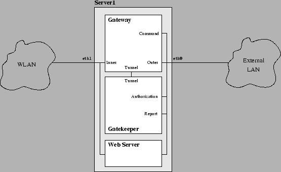
- ALL IN ONE
- The Gateway and the Gatekeeper are in the same server (see Figure 5.1).
Required software
- Uni-Fy software
- web-server (e.g. Apache2)
Required IP addresses
- one public IP address
- a private class of IP addresses that can be routed in the LAN
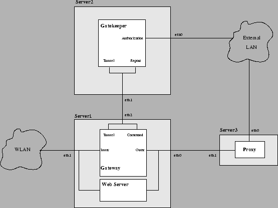
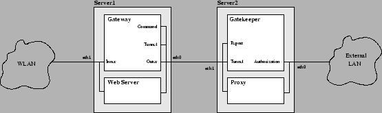
- STANDARD
- The Gateway and the Gatekeeper are in two different server and both
machines have a public IP address (see Figure 5.2).
Required software
- Gateway software (in Server1)
- web-server (e.g. Apache2) (in Server1)
- Gatekeeper software (in Server2)
- proxy software (e.g. Squid) (in Server3)
Required IP address
- two public IP address
- a private class of IP addresses that can be managed by the
network (the traffic must be routed in the LAN)
- TANDEM
- The Gateway and the Gatekeeper are in two different servers and only one
machine has a public IP address (see Figure 5.3).
Required software
- Gateway software (in Server1)
- web-server (e.g. Apache2) (in Server1)
- Gatekeeper software (in Server2)
- proxy software (e.g. Squid) (in Server2)
Required IP address
- one public IP address
- a private class of IP address without requirements: the
traffic from the LAN is managed by the proxy so the class needs not be
routable in the LAN.
Figure 5.1:
Network configuration ALL IN ONE.
|
|
Figure 5.2:
Network configuration STANDARD.
|
|
Figure 5.3:
Network configuration TANDEM.
|
|
|

![[Italian]](images/uk.gif)